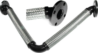
Flanged End Loops
Downloadable PDF: Flanged End Loops 2″, Flanged End Loops 3″, Flanged End Loops 4″
Home » Flanged Loops

Hose:
Type 321 S/S; Braid ; Type 304 S/S
Elbows:
Carbon Steel, Sch 40
Ends:
Plate Flanges (standard), 150# ASA Drilled, Carbon Steel
| Flanged End Loops | |||||||
|---|---|---|---|---|---|---|---|
| Size (In.) | Overall Length OAL (In.) | Live Length LL (In.) | H (In.) | Approx. Spring Force* (Lbs.) | Pressure Ratings (PSI) | Allowable Motions Z, Y or Z | |
| W.P. | Max. Test | ||||||
| 1-1/2 | 28 | 12-1/2 | 12-3/4 | 75 | 472 | 708 | 2" |
| 2 | 32 | 14 | 14-1/2 | 82 | 516 | 774 | |
| 2-1/2 | 35 | 14-1/2 | 15-1/2 | 86 | 387 | 581 | |
| 3 | 39-3/4 | 16-1/2 | 17-3/4 | 93 | 316 | 474 | |
| 4 | 45-3/4 | 18 | 20-1/4 | 127 | 232 | 348 | |
| 5 | 53 | 20 | 23 | 214 | 191 | 286 | |
| 6 | 59-1/4 | 21-1/2 | 25-3/4 | 228 | 165 | 247 | |
| 8 | 71-1/4 | 24 | 30-1/2 | 312 | 234 | 350 | |
| 10 | 84 | 27 | 35-1/2 | 345 | 230 | 344 | |
| 12 | 94-3/4 | 28-1/2 | 39-1/2 | 399 | 161 | 241 | |
*Total force necessary to accomodate full motion, calculated @ 150 PSIG
| Size (In.) | Overall Length OAL (In.) | Live Length LL (In.) | H (In.) | Approx. Spring Force* (Lbs.) | Pressure Ratings (PSI) | Allowable Motions Z, Y or Z | |
|---|---|---|---|---|---|---|---|
| W.P. | Max. Test | ||||||
| 1-1/2 | 32-1/4 | 15-1/2 | 14-3/4 | 75 | 472 | 708 | 3" |
| 2 | 36-1/4 | 17 | 16-1/2 | 82 | 516 | 774 | |
| 2-1/2 | 40 | 18 | 18 | 86 | 387 | 581 | |
| 3 | 45 | 20 | 21-1/2 | 93 | 316 | 474 | |
| 4 | 51-1/2 | 22 | 23 | 127 | 232 | 348 | |
| 5 | 59-1/4 | 24-1/2 | 26-1/4 | 214 | 191 | 286 | |
| 6 | 66-1/4 | 26-1/2 | 29-1/4 | 228 | 165 | 247 | |
| 8 | 79 | 29-1/2 | 34-1/4 | 312 | 234 | 350 | |
| 10 | 93-1/4 | 33-1/2 | 40 | 345 | 230 | 344 | |
| 12 | 104-3/4 | 35-1/2 | 44-1/2 | 399 | 161 | 241 | |
*Total force necessary to accomodate full motion, calculated @ 150 PSIG
| Size (In.) | Overall Length OAL (In.) | Live Length LL (In.) | H (In.) | Approx. Spring Force* (Lbs.) | Pressure Ratings (PSI) | Allowable Motions Z, Y or Z | |
|---|---|---|---|---|---|---|---|
| W.P. | Max. Test | ||||||
| 1-1/2 | 35-3/4 | 18 | 16-1/2 | 75 | 472 | 708 | 4" |
| 2 | 46-1/2 | 20 | 18-3/4 | 82 | 516 | 774 | |
| 2-1/2 | 43-1/2 | 20-1/2 | 19-3/4 | 86 | 387 | 581 | |
| 3 | 49-3/4 | 23-1/2 | 22-3/4 | 93 | 316 | 474 | |
| 4 | 56-1/2 | 25-1/2 | 25-1/2 | 127 | 232 | 348 | |
| 5 | 65 | 28-1/2 | 29-1/2 | 214 | 191 | 286 | |
| 6 | 72 | 30-1/2 | 32 | 228 | 165 | 247 | |
| 8 | 85+1/2 | 34 | 37-1/2 | 312 | 234 | 350 | |
| 10 | 100-1/4 | 38-1/2 | 43-1/2 | 345 | 230 | 344 | |
| 12 | 112-1/4 | 41 | 48-1/2 | 399 | 161 | 241 | |
*Total force necessary to accomodate full motion, calculated @ 150 PSIG
Flanged Loops
Flanged end loops have carbon steel Class 150 plate flanges as standard ends. Raised face flanges, or virtually any other flange configuration can also be ordered. Scheduled 40 carbon steel elbows are also standard, but can be specified in other materials.
As in other configurations of Seismic Loops, choose from either 2″, 3″ or 4″ of motion from center-line. For steam service, EFP recommends placing the loops in either an inverted or horizontal installation when conveying steam. A drain port should also be specified for steam service. We can also add an eyelet at the 90 degree elbow to accommodate a support rod or cable.


