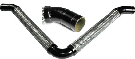
Threaded Loops
Downloadable PDF: Threaded Loops 2″, Threaded Loops 3″, Threaded Loops 4″
Home » Threaded Loops

Hose:
Type 321 S/S; Braid ; Type 304 S/S
Elbows:
Carbon Steel, Sch 40
Ends:
Carbon Steel Sch 40, Male NPT
| Threaded Loops | |||||||
|---|---|---|---|---|---|---|---|
| Size (In.) | Overall Length OAL (In.) | Live Length LL (In.) | H (In.) | Approx. Spring Force* (Lbs.) | Pressure Ratings (PSI) | Allowable Motions Z, Y or Z | |
| W.P. | Max. Test | ||||||
| 1/2 | 22-1/4 | 9 | 9-1/4 | 35 | 1075 | 1613 | 2" |
| 3/4 | 23-3/4 | 10 | 9-3/4 | 41 | 792 | 1188 | |
| 1 | 27-1/2 | 11 | 10-3/4 | 45 | 571 | 857 | |
| 1-1/4 | 19-3/4 | 12 | 12 | 64 | 531 | 797 | |
| 1-1/2 | 31-1/2 | 12-1/2 | 12-1/2 | 68 | 472 | 708 | |
| 2 | 37-1/2 | 14 | 14-1/2 | 82 | 516 | 774 | |
| 2-1/2 | 40-3/4 | 14-1/2 | 15-1/2 | 86 | 387 | 581 | |
| 3 | 45-1/2 | 16-1/4 | 17-3/4 | 93 | 316 | 474 | |
| 4 | 51-1/2 | 18 | 20 | 127 | 232 | 348 | |
*Total force necessary to accomodate full motion, calculated @ 150 PSIG, Note: 1) Maximum operating temperature: 800° F. 2: Other style flanges available.
| Size (In.) | Overall Length OAL (In.) | Live Length LL (In.) | H (In.) | Approx. Spring Force* (Lbs.) | Pressure Ratings (PSI) | Allowable Motions Z, Y or Z | |
|---|---|---|---|---|---|---|---|
| W.P. | Max. Test | ||||||
| 1/2 | 25-3/4 | 11-1/2 | 11 | 35 | 1075 | 1613 | 3" |
| 3/4 | 27-1/4 | 12-1/2 | 11-1/2 | 41 | 792 | 1188 | |
| 1 | 31 | 13-1/2 | 12-3/4 | 45 | 571 | 857 | |
| 1-1/4 | 33-1/2 | 14-1/2 | 13-3/4 | 64 | 531 | 797 | |
| 1-1/2 | 35-3/4 | 15-1/2 | 14-3/4 | 68 | 472 | 708 | |
| 2 | 39-3/4 | 17 | 16-1/2 | 82 | 516 | 774 | |
| 2-1/2 | 44-1/2 | 18 | 18 | 86 | 387 | 5814 | |
| 3 | 50-1/4 | 20 | 20-1/4 | 93 | 316 | 474 | |
| 4 | 59 | 22 | 23 | 127 | 232 | 348 | |
*Total force necessary to accomodate full motion, calculated @ 150 PSIG, Note: 1) Maximum operating temperature: 800° F. 2: Other style flanges available.
| Size (In.) | Overall Length OAL (In.) | Live Length LL (In.) | H (In.) | Approx. Spring Force* (Lbs.) | Pressure Ratings (PSI) | Allowable Motions Z, Y or Z | |
|---|---|---|---|---|---|---|---|
| W.P. | Max. Test | ||||||
| 1/2 | 28-1/2 | 13-1/2 | 12-1/4 | 35 | 1075 | 1613 | 4" |
| 3/4 | 30-3/4 | 15 | 13*1/4 | 41 | 792 | 1188 | |
| 1 | 34-1/2 | 16 | 14-1/2 | 45 | 571 | 857 | |
| 1-1/4 | 37 | 17 | 15-1/2 | 64 | 531 | 797 | |
| 1-1/2 | 39-1/4 | 18 | 16-1/2 | 68 | 472 | 708 | |
| 2 | 44 | 20 | 18-1/2 | 82 | 516 | 774 | |
| 2-1/2 | 48 | 20-1/2 | 22-3/4 | 86 | 387 | 5814 | |
| 3 | 55-1/4 | 23-1/2 | 23-1/2 | 93 | 316 | 474 | |
| 4 | 64 | 25-1/2 | 25-1/2 | 127 | 232 | 348 | |
*Total force necessary to accomodate full motion, calculated @ 150 PSIG, Note: 1) Maximum operating temperature: 800° F. 2: Other style flanges available.
Threaded Loops
Threaded Loops have carbon steel male NPT threaded ends as standard.
As in other configurations of Seismic Loops, choose from either 2″, 3″ or 4″ of motion from center-line. For steam service, EFP recommends placing the loops in either an inverted or horizontal installation when conveying steam. A drain port should also be specified for steam service. We can also add an eyelet at the 90 degree elbow to accommodate a support rod or cable.


